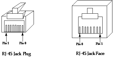
These diagrams are made from copying modtaps I have found that actually worked, not from copying pieces of other pages elsewhere (such as cisco).
Cisco 2500 series routers | |||
|---|---|---|---|
| RJ45 pin | db25 pin | db9 pin | pin name |
| 1 | 5 | 8 | CTS |
| 2 | 8 | 1 | DCD |
| 3 | 3 | 2 | RXD |
| 4 & 5 | 7 | 5 | GND |
| 6 | 2 | 3 | TXD |
| 7 | 20 | 4 | DTR |
| 8 | 4 | 7 | RTS |
Xylogics Annex | |||
| RJ45 pin | db25 pin | db9 pin | pin name |
| 3 | 3 | RXD | |
| 5 | 2 | TXD | |
| 6 | 7 | GND | |

| RJ45 pin | name | crossed RJ45 pin |
|---|---|---|
| 1 | transmit + | 3 |
| 2 | transmit - | 6 |
| 3 | receive + | 1 |
| 6 | receive - | 2 |